- 您现在的位置:买卖IC网 > Sheet目录50 > ANT-433-MHW-RPS-S (Linx Technologies Inc)ANTENNA 433MHZ CENTR FED 79" SMA
3
About Gain Plots
The true measure of the effectiveness of an antenna in any given applica-
tion is determined by the gain and radiation pattern measurement. For
antennas gain is typically measured relative to a perfect (isotropic) radia-
tor having the same source power as the antenna under test, the units of
gain in this case will be decibels isotropic (dBi). The radiation pattern is a
graphical representation of signal strength measured at xed distance from
the antenna.
Gain when applied to antennas is a measure of how the antenna radiates
and focuses the energy received into free space. Much like a ashlight
focuses light from a bulb into a speci c direction, antennas can focus RF
energy into speci c directions. Gain in this sense refers to an increase in
energy in one direction over others.
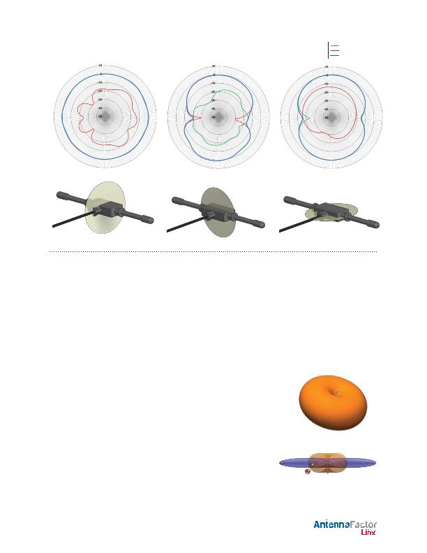
It should also be understood that gain is not
free
, gain above 0dBi in one
direction means that there must be less gain in another direction. Pictori-
ally this can be pictured as shown in the gures to the right. The orange
pattern represents the radiation pattern for a perfect dipole antenna,
which is shaped like a donut. The pattern for an omnidirectional antenna
with gain is shown in blue. The gain antenna is able to work with a device
located further from the center along the axis of the pattern, but not with
devices closer to the center when they are off the axis the donut has
been squished.
Gain is also related to the overall physical size of the antenna, as well as
surrounding materials. As the geometry of the antenna is reduced below
the effective wavelength (considered an electrically small antenna) the gain
will decrease. As well, the relative distance between an electrically small
antenna and its associated ground will impact antenna gain.
159 Ort Lane, Merlin, OR, US 97532
Phone: +1 541 471 6256
Fax: +1 541 471 6251
www.linxtechnologies.com
by
Gain Plots
E / Vertical Gain
H / Horizontal Gain
Total Gain
XZ-Plane Gain
YZ-Plane Gain
XY-Plane Gain
Data Sheet ANT-433-MHW-xxx-x
发布紧急采购,3分钟左右您将得到回复。
相关PDF资料
ANT-433-PW-LP
ANTEN 433MHZ PRMNT 1/4 WAVE WHIP
ANT-433-PW-QW
ANTEN 433MHZ PRMNT 1/4 WAVE WHIP
ANT-433-PW-RA
ANT 433MHZ PRMNT SA 1/4 WAV WHIP
ANT-868-CW-HD
ANTENNA REFERENCE
ANT-868-CW-HW_
ANTENNA 868MHZ 1/2 WAVE DIPOLE
ANT-868-CW-HWR-RPS
ANTENNA 868MHZ 1/2 WAVE RP/SMA
ANT-868-CW-QW
ANTENNA 868MHZ 1/4 WAVE WHIP
ANT-868-CW-RAH
ANTENNA 868MHZ RA 1/4WAVE RPSMA
相关代理商/技术参数
ANT-433-MHW-SMA-L
功能描述:天线 433MHz MHW Dipole SMA, 180’’ Cable
RoHS:否 制造商:Molex 技术类型:Cellular Antenna 频率: 带宽: 尺寸:106.7 mm L x 13 mm W
ANT-433-MHW-SMA-S
功能描述:天线 433MHz MHW Dipole SMA, 79’’ Cable
RoHS:否 制造商:Molex 技术类型:Cellular Antenna 频率: 带宽: 尺寸:106.7 mm L x 13 mm W
ANT-433MR
制造商:LPRS 功能描述:ANTENNA WHIP 433MHZ R/A 制造商:LPRS 功能描述:ANTENNA, WHIP, 433MHZ, R/A 制造商:LPRS 功能描述:WHIP ANTENNA, 430MHZ TO 470MHZ, 50W, 50 OHM; Frequency Min:430MHz; Frequency Max:470MHz; VSWR:1.5; Input Power:50W; Input Impedance:50ohm; Antenna Polarization:Omni; Antenna Dimensions:130mm x 10mm; Frequency Range:430MHz to 470MHz ;RoHS Compliant: Yes
ANT-433MS
制造商:LPRS 功能描述:ANTENNA WHIP 433MHZ 制造商:LPRS 功能描述:ANTENNA, WHIP, 433MHZ 制造商:LPRS 功能描述:WHIP ANTENNA, 430MHZ TO 470MHZ, 50W, 50 OHM; Frequency Min:430MHz; Frequency Max:470MHz; VSWR:1.5; Input Power:50W; Input Impedance:50ohm; Antenna Polarization:Omni; Antenna Dimensions:130mm x 10mm; Frequency Range:430MHz to 470MHz ;RoHS Compliant: Yes
ANT-433-PAOB
制造商:RF Solutions LTD 功能描述:ANTENNA PROANT ONBOARD 434MHZ
ANT-433-PW-LP
功能描述:天线 Perm Mnt Reducd Ht 1/4 Wave Whip 433MHz RoHS:否 制造商:Molex 技术类型:Cellular Antenna 频率: 带宽: 尺寸:106.7 mm L x 13 mm W
ANT-433-PW-QW
功能描述:天线 Permanent Mount 1/4 Wave Whip 433MHz RoHS:否 制造商:Molex 技术类型:Cellular Antenna 频率: 带宽: 尺寸:106.7 mm L x 13 mm W
ANT-433-PW-QW-UFL
功能描述:433MHz Whip, Straight RF Antenna 400MHz ~ 470MHz 3.3dBi Connector, U.FL Panel Mount 制造商:linx technologies inc. 系列:PW 包装:托盘 零件状态:有效 频率组:UHF(300 MHz ~ 1 GHz) 频率(中心/带):433MHz 频率范围:400MHz ~ 470MHz 天线类型:鞭状,直形 频带数:1 VSWR:1.9 回波损耗:- 增益:3.3dBi 功率 - 最大值:- 特性:- 端接:连接器,U.FL 侵入防护:- 安装类型:面板安装 高度(最大值):6.811"(173.00mm) 应用:- 标准包装:24
